
In this article we are going to go through the most common powertrain control function of an mild hybrid electric vehicle (MHEV), focusing on the differences and some similarities compared with a conventional non-hybrid vehicle.
With few exceptions (e.g. electric drive/creep), the following powertrain control functions are not specific to a particular hybrid architecture but common for most of them.
Before going through this article, for a better understanding of hybrid electric vehicles (HEVs) in general and MHEVs in particular, read the following articles:
- Understanding micro, mild, full and plug-in hybrid electric vehicles
- Mild Hybrid Electric Vehicle (MHEV) – introduction
- Mild Hybrid Electric Vehicle (MHEV) – architectures
- Mild Hybrid Electric Vehicle (MHEV) – components (Continental)
- Mild Hybrid Electric Vehicle (MHEV) – electrical architecture
Cold engine cranking
Internal combustion engines (ICE) have mechanical components which are moving relative to each other (e.g. the crank mechanism, the valvetrain, etc.). The friction between these components is reduced thanks to the lubrication system. When the engine is running, an oil film is maintained between the components in order to create hydrodynamic friction. The lower the temperature, the higher the oil viscosity, the higher the friction coefficient, the higher the necessary torque for starting.

Image: Dynamic viscosity and density of the SAE30 lubricant
Credit: Friction in Automotive Engines, H. Allmaier et al.
Another factor that has influence on friction is the oil film thickness. When the engine is not operation, the oil is drained in the oil pan and the oil film thickness is at its minimum. Therefore, at the first engine start, after a long stop period, the friction between the mechanical components is quite high.

Image: FMEP function of oil film thickness
Credit: Overview of automotive engine friction and reduction trends, Victor W. WONG 1, Simon C. TUNG
The combined effect of the low temperature and oil film thickness requires a high starting torque which needs to compensate for the high friction. Therefore belt integrated starter generators (BiSG), used in P0 MHEV architectures, are not suitable for first engine starts. The vehicle must be equipped also with a conventional (pinon-shift-type) starter, which is going to be used for the first or cold engine start.
In case of a BiSG failure, the conventional starter is also used as a backup component to allow engine start.
Conventional Stop & Start (Idle Stop & Start)
When the vehicle is stationary and the engine is operating at idle speed, unnecessary fuel is burnt, hence increasing fuel consumption and exhaust gas emissions. For example, on an NEDC cycle, the vehicle is at standstill (0 kph) for 25% of the time. On a WLTP cycle the standstill time is 13% and on FTP75 is 9%.
Most of the modern vehicle today have engine Stop & Start functions, which are stopping the engine when the vehicle is at stand still. This function can be fulfilled with a conventional starter (connected to the engine through a gear mesh) or with a BiSG.
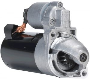 Image: Conventional engine starter |  Image: 48V Belt integrated Starter Generator (BiSG) |
Compared to a conventional starter, there are several advantages of using a BiSG for engine Stop & Start:
- faster start time due to higher output power of the electric machine
- less noise and vibrations due to belt drive (instead of gear mesh)
On a conventional Stop & Start system the engine is shutdown when it’s running at idle speed and the vehicle is stationary. The fuel savings of this system are between 0 … 5 % on real driving cycles, going up to 10% in heavy urban traffic conditions.
Advanced Stop & Start
Compared with conventional Stop & Start, advanced Stop & Start means stopping the engine when the driver brakes and the vehicle speed is below a threshold (e.g. 8 kph) but still moving. Even if the vehicle is still slowly moving, the engine must be at idle and the transmission disconnected before engine shutdown.
The engine disconnection is done by the drive through the clutch pedal on manual transmissions (MT) and through the torque converter on an automatic transmission (AT). The engine is restarted when the driver presses the clutch pedal ( on MT) or releases the brake (on AT).
This function brings additional fuel economy savings since the period with the engine off is extended.

Image: Advanced engine Stop & Start
Advanced Stop & Start function must be able to deal with Change of Mind (CoM) situations. A CoM situation occurs when the driver brakes, the vehicle speed drops below the threshold and the engine shutdown is initiated. If the driver releases the brake pedal, before the vehicle comes to a complete stop, a engine restart is requested (because the driver changed his mind). In this situation a very short engine restart time and fast transmission re-connection are critical for maintaining an acceptable level of vehicle driveability.
The conventional starter contains a pinion which is engaging with the gear on the flywheel before the electric motor delivers torque. The timing between the pinion engagement and motor torque is fixed, they can not be controlled independently. Due to this design constraint, if the pinion is trying to engage before the engine has come to a complete stop, the starter risks to make a loud noise or being damaged. This inconvenient can be resolved by using a specific pinon-shift-type starter which has an independently controlled pinion and motor or use a belt-integrated starter motor (BiSG).
In order to maintain a good level of vehicle driveability, on P0 MHEV architectures, the advanced engine stop & start functions are handled with the high voltage (48V) electric machine (BiSG). The main reason is that the BiSG has a permanent connection with the engine (through the belt) and can deliver a high amount of power in a short time.
Stop-in-motion (Sailing / Coasting)
Stop-in-motion function, also called Sailing or Coasting or Stop & Start Cruising, means disconnecting the engine from the transmission and stopping (or idling) the engine, while the vehicle is travelling at a relative high speed (e.g. 40 kph). The Coasting function is activated when the driver releases slowly the accelerator pedal and the vehicle decelerates (without driver braking).
The rationale behind Coasting is that less fuel is needed to cover the same distance with the transmission disconnected and engine at idle (or off) compared with the situation in which the vehicle is in overrun for a period, followed by acceleration and cruising.
Coasting can be performed with the engine at idle speed (also called Idle Coasting) or with the engine off (also called Off Coasting) For obvious (fuel economy) benefits, the majority of the vehicle manufacturers are developing for MHEVs with Off Coasting control functions.

Image: Vehicle traveled distance with and without Coasting/Sailing
Let’s consider two scenarios. First, the vehicle starts from an initial vehicle speed, with top gear (6th) engaged (overrun) and decelerates (in fuel cut, no fuel is burnt). Due to engine losses, the vehicle will come to a stand still is a relatively short time and distance. In the second scenario, when the vehicle starts to decelerate, the transmission is disconnected and the engine is shutdown. There are no more engine losses to slow down the vehicle and, due to its inertia, the vehicle will travel a longer distance.
Overall, if the Coasting distance is long enough, the fuel efficiency is improved compared to an engine in overrun, acceleration and cruising scenario. In case of a Change of Mind situation (e.g. the driver wants to accelerate the vehicle after a brake event), the system must be capable of handling a fast engine restart. 48V MHEV systems are able to provide a fast engine restart and transmission re-connection to allow the vehicle to accelerate.
Coasting with the engine off, on P0 MHEV architectures, comes with some disadvantages which need to be addressed by the vehicle manufacturer:
- when the engine is stopped, the electric machine can not generate any electrical energy during deceleration phases (since is directly linked to the engine); therefore, only long Coasting distances will provide fuel efficiency benefits; moreover if the engine stop & start events are often, the fuel economy can be reduced, since every engine restart event requires a relatively high amount of fuel (compared with engine running at idle); this situation can be avoided on P2, P3 or P4 MHEV architectures, since the electric machine is on the transmission side
- on engine side, the auxiliary equipment (e.g. AC compressor), will not be powered anymore; in this situation the Climate System can request engine start (or inhibit Coasting) in order to ensure the required temperature in the cabin; a solution is to use 48V electric compressor for AC systems
- if the vehicle is equipped with an automatic transmission, the engine stop will not provide anymore the required power for the transmission’s oil pump; in this situation the AT needs to be equipped either with an oil pressure accumulator or an electric oil pump, in order to provide the necessary oil pressure for the transmission to operate properly
Coasting function is providing the maximum fuel economy benefit for P2, P3 or P4 MHEV architectures, if the vehicle is equipped with 48V electric AC compressor and electric transmission oil pump. Compared to a conventional Stop & Start, a Stop-in-motion (Coasting) function can achieve fuel economy improvements of approx. 5…7 % on WLTC and 7…12 % on FTP75.
Engine load shift
The Brake Specific Fuel Consumption (BSFC) [g/kWh] of an internal combustion engine (ICE) is the ratio between the hourly rate fuel consumption [g/h] and the engine power [kW].
When the vehicle is driving at a constant speed, the engine runs at a specific operating point (speed and torque) which might not be at highest BSFC value. On a P0 MHEV architecture, from the driveability point of view, the total powertrain torque (at the crankshaft) must fulfill the driver’s torque request. The same crankshaft torque level can be maintained with different torque values for the electric machine and internal combustion engine.

Image: BSFC improvement in hybrid electric vehicles
For example, if the driver demands 100 Nm of torque at 2500 rpm, to maintain a constant vehicle speed, the engine is running at a low efficiency, where BFSC is 455 g/kWh. In order to increase the efficiency of the engine, the electric machine is set in generator mode (and charge the battery), with a load torque of -150 Nm.
To compensate for the additional electric load, the engine torque is increased to 250 Nm. The same crankshaft torque level is maintained (250 – 150 = 100 Nm), increasing in the same time the efficiency of the engine, with the BFSC at 320 g/kWh. Thus, the engine load (torque) was shifted from 100 Nm to 250 Nm with an increase in efficiency.
There are several constraints to engine load shift strategy, one of them being the exhaust gas emissions. At high loads, the internal combustion engines have significantly higher emission levels (NOx, particles) compared to medium or low loads.
Torque fill
The internal combustion engine generates torque through the crank mechanism (piston, piston pin, connecting rod and crankshaft). These components have mass and inertia (rotational and translational). Also, the air drawn into the engine has mass, therefore inertia. Because of these design constraints, the engine can not deliver instantaneous torque. If the drive tips-in the accelerator pedal, it takes a while until the engine accelerates to the required operation point (torque and speed).
Electric machines, having only one moving part (rotor) and being governed by electromagnetics laws, can deliver instantaneous torque. A hybrid powertrain can benefit from the electric machines torque delivery in order to improve the overall dynamic performance of the vehicle.

Image: MHEV – engine torque fill with electric machine
Torque fill means to compensate (fill) the torque demand of the driver, which can not be delivered by the engine, with the electric machine torque. Especially in the low speed range, an internal combustion engine has a significant torque lag (delay). If the engine is operating in this region and the driver demands high torque, the difference between what the engine can deliver and what the driver demands is compensated by the electric machine.
For example, if the engine torque is 80 Nm and the driver kicks down the accelerator pedal (full load), demanding 160 Nm, in the fist instance, the electric machine will provide the additional 80 Nm until the engine torque will ramp up, blending out in the end the electric machine torque.
The torque fill function can be regarded as a torque assist function during the transient torque demand phases.
Torque boost
On a MHEV, the total powertrain torque is the sum between the engine torque and electric machine torque. The full load torque characteristic of an engine can be boosted (offset) with the electric machine torque, improving the overall dynamic performance of the vehicle.

Image: MHEV – engine torque boost with electric machine
MHEV vehicles, compared with non-hybrid vehicles, for the same amount of total powertrain torque, have the advantage of improved torque characteristic in the lower speed range. This feature is possible due to the maximum constant torque provided by the electric machine from zero speed.
The electric machine torque boost can be maintained only for a short period of time, the main reasons being the high voltage battery state of charge (low) and the temperature limitation (high) of the power electronics and electric machine.
The torque boost function can be regarded as a torque assist function during the stationary torque demand phases.
Idle charging
In an MHEV, as discussed in the article Mild Hybrid Electric Vehicle (MHEV) – electrical architecture, there are two electric networks, low voltage (12V) and high voltage (48V or above). The electric machine is responsible for providing the required electrical energy for the 12V network and to maintain a minimum state of charge level in both batteries (low and high voltage). Therefore, in some conditions, even if the vehicle is at standstill, the Stop & Start function is inhibited, to allow the engine to provide torque for battery charging and 12V components energy demand.
Idle charging means that the engine is running at idle speed, with the electric machine in generator torque, acting as a load for the engine. When the engine is in idle charging state, the idle speed is slightly elevated (e.g. 1000 rpm) and the engine torque is the sum between idle torque and electric machine torque.
From fuel economy point of view, idle charging is introducing penalties and should be avoided as much as possible. Ideally, the electrical energy should be harvested only during the deceleration phases of the vehicle. When, for various reasons, this is not possible, the electric machine must generate the required electrical energy, even at idle speed.
Energy recuperation
An engine (vehicle) is in overrun when it’s in a deceleration phase, with the engine connected to the wheel through the transmission, and with both acceleration and brake pedals released. During overrun, the vehicle’s inertia is spinning the engine and there is no fuel injection (fuel cut active). In this phase, the engine is acting as a brake to the vehicle, causing it to slow down.
During overrun the vehicle’s inertial force keeps the vehicle in motion while the drag forces (losses or resistant forces) try to stop it. These resistant forces are: the road load, the aero drag, the driveline and transmission drag and the engine drag. These forces can be converted to torque by multiplying them with the wheel radius.

Image: MHEV – energy recuperation with electric machine
Additional to the vehicle and engine losses, the electric machine will be in generator mode, demanding a certain amount of torque Tem [Nm] for charging.
We can write that the total braking torque Tbrk [Nm] of the vehicle, in overrun, is:
\[T_{brk} = T_{veh} + T_{eng} + T_{em} \tag{1}\]where:
Tveh [Nm] – is the vehicle drag (resistive) torque, which includes: road load, aero drag, driveline and transmission losses
Teng [Nm] – are the engine losses, which includes: engine friction and pumping losses and the auxiliary devices torque losses (e.g. AC compressor, oil pump, etc.)
Tem [Nm] – is the electric machine charging torque
The amount of electric machine torque, during overrun, is limited by the maximum deceleration limit of the vehicle. Even if the electric machine is capable of harvesting more electric energy (by increasing the generator torque), it will only recuperate a certain amount, in order to keep the total braking torque within the limits of driveability.
Therefore, energy recuperation means setting the electric machine in generator mode (during overrun) and harvesting electrical energy from vehicle inertia.
Brake regeneration
When the driver presses the brake pedal, the vehicle should decelerate (brake) and eventually come to a complete stop. On a hybrid electric vehicle, the requested brake torque by the driver can be split into electric machine torque and foundation (hydraulic) brake torque.
During a braking event, the hybrid vehicle controller informs the brake controller on the maximum braking torque which can be applied by the electric machine. This limit depends on various factors like: high voltage battery state of charge, inverter or electric machine temperature, etc. Knowing how much braking torque can be applied on the electric machine, the brake controller will only activate the foundation brakes if the driver torque demand is high enough and can not be fulfilled by the electric machine, or if the vehicle speed is low, near stop.

Image: MHEV – brake regeneration with electric machine
In this case, the total braking torque Tbrk [Nm] of the vehicle, when the driver is braking, is:
\[T_{brk} = T_{veh} + T_{eng} + T_{em} + T_{fb} \tag{2}\]where:
Tfb [Nm] – foundation brake torque (hydraulic brakes)
If the driver brakes slightly, the whole brake torque demand can be fulfilled by the electric machine. The higher the power rating of the electric machine, the higher the maximum braking torque which can be applied.
We can define the brake regeneration function as a continuous brake torque control process between the hybrid controller and the brake controller, in which the total brake torque is distributed between the electric machine and foundation (hydraulic) brakes, taking into account a series of factors:
- battery state of charge and power limits
- inverter and electric machine temperature limits
- brake torque distribution between front and rear axles
- vehicle speed (e.g. no brake regeneration during creep speed)
Electric driving (Creep)
Vehicle creep means that the vehicle is slowly moving, at very low speeds. This mode is usually obtained when:
- the transmission has a gear engaged (usually 1st gear)
- the clutch is closed (for manual transmissions)
- the accelerator pedal is not pressed
- the engine is at idle speed
On a conventional non-hybrid vehicle Creep mode is also called Idling in Gear.
Vehicle equipped with automatic transmissions (AT) can go into creep mode quite easily. With Drive (D) mode selected and the vehicle at standstill, when the driver is releasing the brake pedal, the vehicle starts to slowly move (creep) due to the idle torque being transmitted at the wheels.
For a vehicle with manual transmissions (MT), in order to creep from standstill, with 1st gear engaged and clutch pedal fully pressed, the driver has to release slowly the clutch pedal and start transmitting the engine’s idle torque to the wheels. If done in a controlled manner, the idle controller of the engine, in order to keep the idle speed, will slowly build up engine torque which will move the vehicle.
Creep mode can be also entered when the vehicle is driving at a constant speed (or accelerating) and the accelerator pedal is released. The vehicle will slow down due to powertrain and road losses (drag). When the engine speed will approach the idle speed target, the engine’s idle controller will regulate the engine torque and the vehicle will keep moving slowly.
Depending on the engaged gear, vehicle mass, gear ratio and engine idle speed, the creep speed of the vehicle is between 5 – 10 kph.
Creep mode is a very inefficient operation point for the engine, mainly because the volumetric efficiency of the engine is around minimum.
")
Image: Valeo 48V Electric Rear Axle Drive (ERAD)
A P3 or P4 mild hybrid vehicle architecture can support vehicle creep in electric mode. Performing creep mode with the electric machine improves the overall energy efficiency, because the internal combustion engine can be shutdown. Being at low speed, the electric machine can deliver its maximum torque, which is enough to launch and keep the vehicle at creep speed.
For any questions, observations and queries regarding this article, use the comment form below.
Don’t forget to Like, Share and Subscribe!