
Table of Contents
- Internal combustion engine operation
- Simple flywheel
- Downsizing & Downspeeding
- Dual Mass Flywheel operation and components
- Long Travel Damper Dual Mass Flywheel
- Flexible flywheel
- Flexible Long Travel Damper Dual Mass Flywheel
- Dual Mass Flywheel for Double Clutch Transmission
- Dual Mass Flywheel driveplate
- Dual Mass Flywheel with centrifugal pendulum-type absorber
- Damped Flywheel Clutch (DFC)
- Dual Mass Flywheel for Continuously Variable Transmission (CVT)
- Planetary gear Dual Mass Flywheel
Internal combustion engine operation
The vast majority of road vehicles are equipped with internal combustion engines. Due to the working principle of the internal combustion engine, there are torsional vibrations generated at the crankshaft. The combustion process generates an extremely rapid rise of pressure inside the cylinder, during the power stroke, which results in a torque output with peaks. The pressure generated in the cylinders applies a force on the top of the piston, which is transmitted through the connecting rod and allows the crankshaft to turn. The pulsating torque generated by the cylinders causes the vibrations at the crankshaft.
 speed")
Image: Engine speed amplitude at idle (low) speed
On a reciprocating piston engine the pressure gradient in the cylinder during the four cycles produces an uneven torque on the crankshaft. The pulsating torque generated at the crankshaft makes the engine speed to be also pulsating. For example, if we measure the idle speed of an engine, with a sampling time of 100 ms or less, we can see that the engine speed in not constant at around 975 rpm but rapidly oscillating between 925 and 1050 rpm.
All these rotational vibrations are transmitted further into the drivetrain and can affect the durability of its components. These vibrations can create gear rattle, body boom and tip-in/tip-out vibrations in the driveline which produce considerable noise and loss in driving comfort.
Simple flywheel
On each power cycle, the combustion of the air-fuel mixture greatly accelerates the crankshaft. During the other three cycles (intake, compression and exhaust), the crankshaft decelerates sometimes strongly and sometimes less strongly. To enable the engine to mainly run smoothly at lower speeds a centrifugal mass, the flywheel, smooths out these rotational speed irregularities to a certain extent.
A 4-cylinder four cycle internal combustion engine has a firing interval of 180°. For example, if the 4-cylinder engine runs at 3000 rpm, there are 6000 ignitions per minute, which corresponds to 100 ignitions per second. The engine rotational speed irregularities are therefore very slight.
The lower the engine speeds the clearer the engine rotational speed irregularities appear in the form of torsional vibrations. At 1200 rpm, there are approximately 40 ignitions per second, which means that a power cycle only occurs every 25 milliseconds. The engine rotational speed irregularities and therefore the torsional vibrations are very marked in this engine speed range.
If these torsional vibrations are transferred to the gearbox, without being damped, resonance vibrations arise in the gearbox and in the drivetrain. In turn, these resonance vibrations cause boom and humming noises or gear rattle. Also, higher resonance vibrations can damage the components in the gearbox and drivetrain in the long term. Without appropriate damping of torsional vibrations, the driving comfort at low engine speeds is unacceptable and low engine speed fuel saving driving is also not practical.
The reduction of the rotational vibrations of the crankshaft can be achieved by using a flywheel. A flywheel is a mechanical component designed to store rotational energy (kinetic energy). Flywheels resist changes in rotational speed due to their moment of inertia. The amount of energy stored in a flywheel is proportional to the square of its rotational speed and its mass.
\[E = \frac{J \cdot \omega^{2}}{2}\]where:
E [J] – kinetic energy stored in the flywheel
J [kg·m2] – flywheel moment of inertia
ω [rad/s] – flywheel angular velocity
The higher the inertia or the angular velocity of the flywheel, the higher the stored energy.

Image: 1.3 JTD 16v Multijet engine
Credit: Fiat
In the internal combustion engine case, the flywheel is attached at the end of the crankshaft. How it works:
- during the power stroke of the engine, the flywheel stores the kinetic energy
- during the intake, compression and exhaust strokes, the flywheel releases the kinetic energy
This way, the spikes in torque are dampened during the power stroke and distributed through the whole cycle of the engine. This effect applies for all the cylinders of the engines. The higher the number of cylinders in an engine, the smoother the output torque/power.

Image: Engine torque during a 4-stroke cycle
The type of the engine (diesel/petrol), the number of cylinders, the engine cubic capacity and the specific power [kW/L] of the engine has significant impact on the rotational vibrations of the crankshaft. For example, high capacity atmospheric, petrol/gasoline engines, have low torque at low speed. Also its moving parts, pistons, connecting rods, crankshaft have higher mass, which means higher inertia thus more manageable spikes in rotational speed. These factors combined makes the output torque ripples (oscillations) manageable with a standard flywheel.
Downsizing & Downspeeding
A major task of the automotive industry in recent years has been to reduce consumption and CO2. One effective measure for achieving this goal is to exploit even lower engine speeds for driving. Torque is increased to achieve this without losing power. Doing so allows the engine to run only very slightly above idle speed and therefore in an extremely consumption-efficient range. One challenge is to achieve adequate powertrain isolation even for these low engine speeds and thus provide drivers with their usual level of comfort.
The rapid development of vehicle technology over the last few decades has brought ever higher performance engines paralleled by an increased demand for driver comfort. Weight-saving vehicle concepts and wind tunnel-optimised bodies now allow other sources of noise to be perceptible to the driver. In addition, lean concepts, extremely low-speed engines and new generation gearboxes using light oils contribute to this.
In order to improve fuel consumption and reduce exhaust gas emissions, recent engine development strategies included engine downsizing and downspeeding.
 Image: Downsizing for V6 to L4 |
 Image: Effect of number of cylinders on speed oscillation |
- downsizing means that the total engine volumetric capacity is reduced by reducing the number of cylinders (e.g. from 6 cylinders to 4 cylinders), but maintaining the torque/power output (usually using intake air boosting, variable valve lift technologies, direct fuel injection, etc.)
- downspeeding means that the peak engine torque is obtained at lower engine speed (e.g. from 2500 rpm to 1500 rpm), achieved for example by using dual-stage turbocharging, electric air compressors, etc.
With other words, downsizing and downspeeding are processes whereby the speed / load operating point is shifted to a more efficient region through the reduction of engine capacity whilst maintaining the full load performance via pressure charging.

Image: Ford engine downsizing torque output
Credit: Ford
The combination of smaller inertia of the moving components with the higher torque at low engine speeds generates higher rotational vibrations at the crankshaft. Also, with more stringent CO2 and exhaust gas emissions being impose worldwide, more engine downsizing and down speeding strategies are being put in place by internal combustion engines manufacturers. The side effect of this strategy is that more vibrations are generated at the crankshaft which are being transferred in the driveline.

Image: Engine downsizing trend
Credit: Global Insight & Honeywell
Dual Mass Flywheel operation and components
There are different technologies available to filter out the rotational vibrations of the crankshaft. All these technologies can be classified into three main categories:
- active damping: in this case an active component (damper) is used, which can generate an opposite force to the crankshaft vibration force; this way the vibrations are cancelled out resulting in a smooth rotation of the crankshaft; this method gives the best vibration reduction performance but comes with a high cost; also, the active component requires an external energy supply and does not have the required reliability for automotive applications
- semi-active damping: it’s similar with the active damping technology but with less external power requirement
- passive damping: implies the usage of a passive component, which does not require external energy but can dissipate energy; the most common applications usually consist of a spring and damper; this is the most cost-effective solution with a reasonable good vibration reduction characteristic.
One efficient and cost effective solution to reduce the rotational (torsional) vibrations is to use a DMF, which is the abbreviation for Dual Mass Flywheel. The dual mass flywheel (DMF) is a passive damping component and its main function is to isolate the driveline/transmission from the vibration generated by the internal combustion engine. This technique will also improve the overall noise behaviour of the vehicle and reduce fuel consumption.
 Image: Working principle of a conventional flywheel |
 Image: Working principle with a dual mass flywheel (DMF) 1 – engine |
Compared with a conventional flywheel, which has one mass, a standard DMF consists of a primary mass and a secondary mass. The two masses are decoupled and connected through a system with springs and dampers. Both masses are supported by a deep groove ball bearing or plain bearing so they can rotate against each other. The spring rate and the damping characteristic are crucial in determining
the operating performance of a dual mass flywheel.
The primary mass (2) (see figure below) is tightly bolted to the crankshaft, has the starter ring gear (1) attached and it’s driven by the engine. It encloses, together with the primary cover (6), a cavity which forms the arc spring channel.
")
Image: Section through a dual mass flywheel (DMF)
Credit: LuK
The main components of the spring-damper system are the arc springs (3). They sit in guides in the arc spring channels and cost-effectively fulfil the requirements of an “ideal” torsion damper. The guides ensure correct guidance of the springs during operation and the grease around the springs reduces wear between themselves, the guides and the channels.
Between the primary and secondary mass, the torque is transferred via the flange (5). The flange is riveted to the secondary mass (7) with its wings sitting between the arc springs.
The secondary mass helps to increase the mass moment of inertia on the gearbox side. Vents ensure heat created during clutch friction is dissipated efficiently. As the DMF has an integral spring-damper system, a rigid clutch disc without a torsion damper is normally used.
")
Image: Standard dual mass flywheel (DMF)
Credit: LuK
1 – starter ring gear
2 – primary mass
3 – arc springs
4 – plain bearing
5 – flange
6 – primary cover (cross-section)
7 – secondary mass
 components")
Image: Dual Mass Flywheel (DMF) components
Credit: Valeo
1 – starter ring
2 – primary mass
3 – friction washers
4 – bearing or bushing
5 – drive plate
6 – arc springs & spring guides
7 – cover
8 – secondary mass
In a vehicle with a conventional flywheel and torsion-damped clutch disc, the torsional vibrations in the idling range are transferred practically unfiltered to the gearbox and cause the gear teeth edges to knock together (gearbox rattle). On the other hand, the spring-damper system of the DMF filters out torsional vibration caused by the engine. This prevents gearbox components knocking against each other – rattling does not occur and the driver’s demands for higher comfort are fully met.
The functioning principle of a dual mass flywheel is simple and efficient. Due to the additional mass on the transmission input shaft, the vibration torque range, which is normally between 1200 rpm and 2400 rpm with original torsion dampers, is moved to a lower resonance speed range. This ensures excellent damping of engine vibration even at idle speed.
 Image: Transfer of torsional vibrations with conventional flywheel |
 Image: Transfer of torsional vibrations with DMF |
The dual mass flywheel (DMF) made it possible to isolate the rotational vibrations of the internal combustion engine from the rest of the drivetrain. The undesired gearbox rattling noises were eliminated and body boom considerably reduced. It also became possible to drive the vehicle at very low engine speeds, by increasing low-end torque, therefore reducing fuel consumption.
There are many other operating points which must also be considered when designing a dual mass flywheel (DMF). Firstly, the engine must be started and later stopped at the end of the journey and perhaps also at traffic lights. The drive itself begins with the vehicle launch. Changes in the accelerator pedal position as well as gear changes cause load changes in the drivetrain, or the vehicle coasts without load. These are only a few of the additional operating points in which there is a high demand for comfort.
In all these operating points, the DMF substantially reduces noise, rotational vibration and overall vehicle comfort.

Image: The effect of the DMF on vehicle comfort
Credit: LuK
The primary mass is connected to the crankshaft of the internal combustion engine. The primary mass of the DMF and the crankshaft are combined together to form a whole inertia. Compared to a conventional flywheel, the primary mass of the DMF is significantly more flexible, which helps to relieve the crankshaft load. In addition, the primary mass – together with the primary cover – forms the arc spring channel which is typically divided into two sections, separated by the arc spring stops.
The primary mass is a steel stamped component with a sufficient mass moment of inertia. In certain cases, it could be made from cast iron. For engine starting, the starter ring gear is positioned on the primary mass. Depending on the type of DMF, it is either welded or cold pressed on.
 - spring") Image: Standard dual mass flywheel (DMF) – spring 1 – primary cover |  - primary mass") Image: Standard dual mass flywheel (DMF) – primary mass 1 – starter ring gear |
The cover is welded to the primary mass to form a sealed chamber containing the curved springs, spring guides and the lubricant.
 cover")
Image: Dual Mass Flywheel (DMF) cover
Credit: Valeo
The engine torque is transferred from the primary mass to the secondary mass via the arc springs and the drive plate. Thanks to the bearing between the primary and secondary mass, independent radial movement of the masses is possible. As with a rigid (single-mass) flywheel, the power output is through the clutch, which is bolted to the secondary mass. The crucial difference, however, is that the engine torque is now largely free of rotational vibration, i.e. it is modulated. Because of this, a clutch disc with torsion damping can be dispensed with in most cases if a DMF is used.
 secondary mass")
Image: Dual Mass Flywheel (DMF) secondary mass
Credit: Valeo
The secondary mass is a cast iron component. One side is machined to form the friction surface of the disc. The secondary mass transmits the engine torque to the clutch, and further to the gearbox and the wheels.
 Image: Standard DMF – secondary mass – gearbox side 1 – clutch bolting surface |  Image: Standard DMF – secondary mass – engine side 1 – rivet hole |
The bearing in the primary mass serves as a rotating connection with the secondary mass. It not only has to absorb the weight-related radial forces of the secondary flywheel and the clutch, but also the axial forces generated by the release force when disengaging.
 - bearing")
Image: Standard dual mass flywheel (DMF) – bearing
Credit: LuK
1 – bearing tower
2 – plain bearing
3 – ball bearing
A dual mass flywheel (DMF) uses two different types of bearings:
- ball bearing: when development of the DMF started, large ball bearings could be used because of the relatively simple design of the internal components; however, the constantly rising demands on the rotary vibration damping made additional components necessary in the DMF; for this reason, further construction space had to be created; this led to a systematic reduction of the diameter of the ball bearing; small ball bearings allow the space-neutral integration of additional rotary vibration dampers and, in this way, increase the efficiency of the DMF.
- plain bearing: in comparison with ball bearings, plain bearings take up less space and are more simply designed; in spite of their low manufacturing costs, they can be universally used and, if necessary, can be designed to allow axial motion.
 - ball bearing") Image: Standard DMF – ball bearing |  - plain bearing") Image: Standard DMF – plain bearing |
The primary mass is fitted with a turned hub on which the large-size ball bearing is fitted. A hub flange with the bearing seat (turned or drawn) is mounted onto the primary mass. The bearing seat can be adjusted to mount a small ball bearing – as shown here – or a plain bearing.
 - bearing size")
Image: Standard dual mass flywheel (DMF) – bearing size
Credit: LuK
1 – primary mass with bearing seat on hub
2 – hub
3 – large-size ball bearing
4 – cross section of primary mass with hub and large-size ball bearing
In comparison with ball bearings, plain bearings take up less space and are more simply designed. In spite of their low manufacturing costs, they can be universally used and, if necessary, can be designed to allow axial motion.
 - plain bearing") Image: Standard dual mass flywheel (DMF) – plain bearing 1 – coated plain bearing bushing |  - small bearing") Image: Standard DMF – small bearing 1 – small-size ball bearing |
The task of the drive plate is to transfer torque from the primary mass via the arc springs to the secondary flywheel; in other words, from the engine to the clutch. The drive plate is tightly riveted to the secondary mass with its wings (arrows) sitting between the arc spring channel of the primary mass. The gap between the arc spring stops in the arc spring channel is big enough to enable the drive plate to rotate.
The rigid drive plate is riveted directly to the secondary mass. This allows the use of drive plate wings with different symmetries, which has a positive effect on the isolation of vibration. The simplest form is the symmetrical drive plate, where pull and push sides are identical. Thus, load is applied on the arc springs via both outer and inner areas of the end coil.
 - flange") Image: DMF – drive plate 1 – drive plate wings |  - flange") Image: DMF – drive plate 1 – spring aperture |
The key function of the DMF is to isolate the transmission from the vibration generated by the engine. In order to compensate for the constantly increasing engine torques while the installation space remains the same, the windup curves of the arc springs must rise more steeply. Consequently, their vibration damping capacity deteriorates. Using friction-free internal dampers helps to improve vibration elimination during acceleration. Both the drive plate and the side panels are designed with spring apertures which house straight pressure springs. The excellent vibration damping characteristics of the DMF with internal damper are guaranteed even in the highest torque ranges.
At high engine speeds, the resulting centrifugal forces press the arc springs to the outside against the guides and the coils are disabled. Consequently, the arc spring stiffens and spring action is partly lost. In order to maintain sufficient spring action, straight pressure springs are mounted in the drive plate. Owing to their lower mass and mounting position on a smaller radius, these springs are subject to a lower centrifugal force. Additionally, the convex shape of the upper edge of the spring windows helps to minimise friction. This ensures that neither friction nor the effective spring rate will increase as engine speeds go up.
 - flange")
Image: Dual mass flywheel (DMF)
Credit: LuK
1 – drive plate
2 – retaining panel
3 – friction lining
When an attempt is made to adjust the engine speed very quickly to the speed of the gearbox input shaft, sudden peak loadings occur, so-called impacts. In this way, for example, an impact may be caused by a sudden engagement, leading to stalling of the engine. Here, the arc springs are briefly fully compressed, leading to a disproportionate increase in the loading on the drive plate. In the case of rigid drive plates and those with internal damping, frequent impacts may lead to material deformation, culminating in breakage of the drive plate wings.
One way to compensate for impacts and minimise material damage is a drive plate with a friction clutch. In this case, the drive plate is designed as a diaphragm spring. It is pre-tensioned and positioned by two riveted retaining plates with a thin friction lining. In cross-section, this forms a fork-shaped fixture which allows slipping of the drive plate. In the case of an impact, the drive plate can now rotate in the retaining plates. The surplus energy is dissipated as friction heat. In this way, the load on the drive plate wings is minimised.
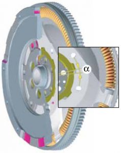
Image: Standard DMF – friction control disc
Credit: LuK
During the start-up process, the DMF operates briefly in the resonant frequency range. When this happens, the drive plate wings repeatedly hit the arc springs with unbraked force, producing noise as they do so. An effective countermeasure here is an additional friction device, the friction control plate. This has the effect of delaying the rotation of the drive plate within a defined working range. As a result, the drive plate can be rotated over the secondary mass in the range of clearance angle (α) without noticeable resistance. Only outside the clearance angle, i.e. at greater angles of rotation, does the additional friction come into effect. In this way, the noises produced when starting up or changing the load can be eliminated.
During engine start-up, a high angular deflection occurs between the primary and secondary mass. To limit this deflection and help improve engine start-up, friction washers are added on certain applications. They do not operate in drive mode.
 friction washers")
Image: Dual Mass Flywheel (DMF) friction washers
Credit: Valeo
DMF systems help to improve the noise behaviour of the vehicle by using special torsion damper designs. As a direct result, less noise is generated and fuel consumption is reduced. In order to make ideal use of the available space, a coil spring with a large number of coils is fitted in a semicircular position. The arc spring lies in the spring channel of the DMF and is supported by a guide. Under operation, the coils of the arc spring slide along the guide and generate friction and thereby damping. In order to prevent wear on the arc springs, the contact surfaces are smeared with grease. The optimised shape of the spring guides helps to reduce friction significantly. Besides improved vibration damping, arc springs help to reduce wear.
 Image: Standard DMF – arc spring 1 – guide |  Image: Standard DMF – single spring |
Thanks to the diversity of arc spring designs, a dual mass flywheel system can be manufactured to precisely match the individual load characteristics of each vehicle type. Arc springs of various designs and characteristics are used. The most frequent types are:
- single-stage springs
- two-stage springs: either in a parallel arrangement in one of various different layouts, or in-line arrangement
- damping springs
In practice, the spring types are applied in various different combinations. The spring rate and the damping characteristic are crucial in determining the operating performance of a dual mass flywheel.
Benefits of the arc spring:
- high friction at large rotation angle (start-up process) and low friction at low rotation angle (overrun)
- lower actuation force (spring rate) because of the flexible space utilisation (in comparison with systems with multiple single springs)
- impact damping can be integrated (damping spring)
 Image: Standard DMF – single-stage parallel spring |  Image: Standard DMF – two-stage parallel spring |
The basic version of the arc spring is a single spring. This is characterised by its large spring volume and resulting high damping capacity. Because of its simple design, however, it only offers limited possibilities for satisfying rising demands for comfort. For this reason, today’s DMFs are seldom fitted with single springs.
The arc springs in most frequent use today are single-stage parallel springs. It consists of an external and internal spring, of about the same length. The two springs are arranged in parallel. Their individual characteristics add up to the spring set curve.
 2-stage curved spring")
Image: DMF two-stage curved spring
Credit: Valeo
In two-stage parallel springs, two arc springs are again arranged one inside the other. The internal spring, however, is shorter, thus engaged later. The wind-up curve of the external spring is matched to the requirements of the vehicle when the engine starts. Here, load is applied only on the softer external spring, enabling the system to pass the critical resonance speed range faster. In the higher and maximum torque ranges, load is exerted on the internal spring as well. Both external and internal springs work together in the second stage. The interplay of both springs provides good damping at all engine speeds.

Image: Standard DMF – three-stage parallel spring
Credit: LuK
Three-stage arc spring consists of one external spring and two internal springs of different lengths arranged in-line. This design combines the benefits of the parallel and in-line arrangements and therefore allows for optimum torsion damping at each engine torque.
The configuration of the springs in the first-generation dual mass flywheels was identical to conventional torsion dampers, where the pressure springs are mounted in a radial direction close to the centre and can therefore provide only limited spring capacity. This design was sufficient to isolate vibration in 6-cylinder engines, as these produce low resonance speeds.
In contrast, 4-cylinder engines induce higher irregularities and consequently higher resonance speeds. Repositioning of the springs towards the outer edge and the use of high-pressure spring diameters increased the damper capacity 5 times without requiring more space.

Image: DMF design evolution
Credit: LuK
The primary side of the dual mass flywheel (shown in blue) consists of formed sheet metal parts which make the spring channel, and a cast hub. The secondary side of the dual mass flywheel (shown in red) consists of a cast disc, into which the torque is transmitted from the flange. The secondary side is mounted in the primary side over a ball bearing. The heart of the system is the arc spring system.
Long Travel Damper Dual Mass Flywheel
Valeo’s Long Travel Damper Dual Mass Flywheel (LTD DMF) offers improved acoustic comfort and reduces vibrations. The LTD DMF significantly reduces perceived vibrations and engine noise. This represents a major step forward in powertrain filtration technologies. This technological improvement is especially important because the latestes engines with improved fuel consumption have higher torque and, consequently, generate greater vibrations, especially at low speed. The LTD DMF absorbs torque vibrations generated by the engine to the transmission, thereby increasing the comfort of the vehicle’s occupants.
 Long Travel Damper (LTD)")
Image: Dual Mass Flywheel (DMF) Long Travel Damper (LTD)
Credit: Valeo
A – engine side
B – transmission side
1 – drive plate No. 1
2 – hysteresis washer
3 – drive plate with springs
4 – back plate
5 – drive plate No. 2
The LTD technology is based on two sets of three springs operating in series and synchronised by a back plate. The straight springs are less sensitive to the centrifugal load than the curved springs. This provides less friction, hence the filtering is better than with the curved springs.
In addition to the known dual mass flywheel technology, the LTD DMF integrates a long travel damper developed by Valeo for torque converters in automatic transmissions (AT). This combination allows it to provide optimal filtration, especially during engine start-up, thanks to a maximum angular displacement of 80 deg, as well as an exceptional performance level in all engine regimes.
Valeo’s long travel damper dual mass flywheel offers comfort levels previously unknown on the most fuel-efficient engines. The NVH (Noise Vibration Harshness) level and ease of gear changes offer remarkable driving comfort for the most vibration-prone engines.
 Image: LTD DMF – no load |  Image: LTD DMF – under load |
Flexible flywheel
The crankshaft bends under the force of the strong combustion pressure inside the engine cylinders. This generates the deflection of the crankshaft and an axis wobbling on the flywheel, which is bolted at the end of the crankshaft. Mechanical stress occurs between the bearings and crankshaft, generating vibrations. If not filtered, the result is a roaring noise caused by the engine, a flywheel axial vibration and a potential increased vibration at the clutch pedal.

Image: Advantage of flexible flywheel
Credit: Valeo
The flexible flywheel filters the axial vibrations transmitted through the engine crankshaft. This is achieved by adding a flexible plate at the engine side of the flywheel mass. Deformation of the crankshaft continues, but it is not transmitted to the flywheel thanks to the flexible plate.
Advantages of the flexible flywheel:
- reduced engine noise at high engine speeds
- reduced bending stress on the crankshaft
- reduced level of vibration on the clutch pedal

Image: Flexible flywheel
Credit: Valeo
A – crankshaft side
B – clutch side
Flexible Long Travel Damper Dual Mass Flywheel
The flexible function can be present both on the rigid flywheel and on the Dual Mass Flywheel. On a DMF, the flexible plate is attached to the primary flywheel and a multi-stage hub is used to reduce the pressure in the crankshaft fitting bolts.

Image: Flexible long travel damper dual mass flywheel
Credit: Valeo
1 – flexi-plate
2 – primary mass
3 – curved springs & spring guides
4 – Long Travel Damper
5 – cover
6 – starter ring
7 – secondary mass
Dual Mass Flywheel for Double Clutch Transmission
The flywheel used in the double clutch transmissions (DCT) is a special form of the LuK DMF. As in the conventional DMF in manual gearboxes, there is a primary and a secondary side. However the secondary side, in contrast to the conventional DMF, is not a fixed part of the DMF, so it is not designed as a flywheel mass but in the form of a drive plate. It serves only as a connection between the primary mass and the double clutch.
The secondary mass is replaced in this case by the weight of the double clutch, which is fitted on an input shaft (hollow shaft) of the gearbox. There is also no need for the direct bearing connection of the opposed masses, which is realised in the form of ball or plain bearings in the conventional DMF.

Image: Standard DMF – for DCT
Credit: LuK
1 – primary mass with arc spring
2 – drive plate with internal toothing to engage with the coupling wheel of the double clutch
3 – tension ring
4 – cover for primary mass with starter ring gear
The flywheel used in a DCT is a special form of the DMF. As in the conventional DMF in manual gearboxes, there is a primary and a secondary side. However the secondary side, in contrast to the conventional DMF, is not a fixed part of the DMF, so it is not designed as a flywheel mass but in the form of a drive plate. It serves only as a connection between the primary mass and the double clutch.
The secondary mass is replaced in this case by the weight of the double clutch, which is fitted on an input shaft (hollow shaft) of the gearbox. There is also no need for the direct bearing connection of the opposed masses, which is realised in the form of ball or plain bearings in the conventional DMF.

Image: Standard DMF for DCT
Credit: LuK
1 – tension ring
2 – coupling ring of the double clutch
Another difference from the conventional DMF is the lack of a friction surface on the secondary side. This too is located in the double clutch. There, the central plate bears the friction surfaces for both clutches. Instead of the friction surface on the DMF, an internally toothed flange is used. The coupling ring of the double clutch engages with this flange.
As the two engaging gearwheels would produce noise due to backlash, a tension ring is fitted as a countermeasure. This pre-tensions the two gearwheels so that there is no play between the tooth surfaces. In some models, the tension ring has to be compressed with a special tool before the gearbox is fitted.
Driveplate Dual Mass Flywheel

Image: DMF with driveplate
Credit: LuK
1 – driveplate
Since 2008, a new gearbox generation has been fitted in some Audi models. These gearboxes can be recognised by the different arrangement of the differential. This is now in front of the clutch in the direction of travel. As a result, the power flow to the left drive shaft has to be transmitted straight through the bell housing by a flanged shaft. Because of this, use of a conventional DMF is no longer possible. In order to equip this drive concept with effective flywheel damping, the DMF with driveplate was developed.
The driveplate is an adapter plate formed from sheet steel, which is riveted on to the DMF at the usual fixing points. The driveplate, like a torque converter in an automatic gearbox, is bolted to the outer radius of the coupling disc on the engine side.

Image: DMF with driveplate – cross-section
Credit: LuK
1 – riveted joint
2 – flanged shaft of the gearbox
3 – driveplate
4 – engine coupling disc
5 – DMF
Functions of the driveplate:
- it provides the space required for the penetration of the flanged shaft
- it transfers the engine torque via the bolted joint on the coupling disc to the riveted joint on the DMF
Unlike the conventional DMF, the secondary mass has a needle bearing on the gearbox input shaft. This results in a favourable weight distribution between the two flywheels. The internal construction of the DMF is practically identical to that of the other types described.
Dual Mass Flywheel with centrifugal pendulum-type absorber
For most of the engine applications, the torsional vibrations could be reduced with dual mass flywheel, assuming that comfortable driving at low engine speeds was possible. In addition to engine speed and number of cylinders, engine rotational speed irregularities greatly depend on how much torque the engine can produce at low speeds. Modern petrol and diesel engines which produce a high level of torque at a low speed cause greater torsional vibrations compared with the engines that produce less torque of the same engine speed.
These high torque engines place very high demands on the torsional vibration damping system and the engine vibrations can no longer be satisfactorily eliminated using conventional dual mass flywheels.
An innovation to efficiently eliminate two engine torsional vibrations is the dual mass flywheel with centrifugal pendulum absorbers. It is best suited for the torque characteristic and the torsional vibration behaviour of modern engines because it can reduce the lower limit of the usable speed range of the engine, which means that fuel and CO2 savings are possible.

Image: DMF with centrifugal pendulum absorber
Credit: BMW
The centrifugal pendulum absorbers are an additional functional unit in the dual mass flywheel, which contain four pendulum masses on the secondary mass. The springs used in the primary mass absorb relevant vibrations, while the remaining engine rotational speed irregularities are effectively eliminated by the pendulum masses.
The pendulum masses are arranged at 90° intervals and amounted so that they can oscillate freely in the direction of rotation. The weight of the pendulum masses and the curved radius of the bearing track are precisely coordinated to the torsional vibration or behaviour of the engine so that they oscillate contrary to the torsional vibrations of the engine. With this opposing effect of the pendulum force, the disturbing torsional vibrations of the engine are reduced very effectively upstream of the gearbox.
At low engine speeds when the disturbing torsional vibrations are particularly high, the pendulum swings are correspondingly large and so work effectively against the torsional vibrations of the engine. With increasing engine speed the torsional vibrations of the engine become weaker and have a higher frequency. Due to the interplay a pendulum force on the curved shape of the pendulum bearing the pendulum swings also become less severe and have a higher frequency.

Image: DMF with centrifugal pendulum-type absorber
Credit: LuK
The counter vibrations are just smoothly to fit with the engine speed until an engine speed is reached where there are no longer any noticeable torsional vibrations. Dual mass flywheel with centrifugal pendulum absorbers cannot be differentiated from dual mass flywheel without centrifugal pendulum absorbers purely by their external appearance
With centrifugal pendulum absorber technology, engine rotational speed irregularities are eliminated more effectively than was possible with conventional dual mass flywheel. Centrifugal pendulum absorber technology is particularly effective on low consumption and high torque engines, with a low number of cylinders as these naturally run less smoothly.
Centrifugal pendulum absorber technology enables low engine speed in economic driving with high acoustic driving comfort. Centrifugal pendulum absorbers are not used instead of the dual mass flywheel but instead integrated as an additional functional unit.
The DMF with centrifugal pendulum-type absorber has been developed to further increase damping capacity at low engine speeds. Using no additional installation space, a further additional mass (the centrifugal pendulum-type absorber) has been added to the two main masses in the DMF. It consists of three or four double pendulum masses which sit on the DMF drive plate. They are suspended on two studs which move in kidney-shaped paths in the pendulum masses and in the drive plate.

Image: Standard DMF – centrifugal pendulum-type absorber
Credit: LuK
1 – pendulum mass
Oscillation of the pendulum masses is induced by the ignition frequency of the engine. The pendulum, however, is not directly in the power flow. As a result of inertial torque, the pendulum masses move in opposition to the initial oscillation and, in this way, act as oscillation dampers. The total weight of the pendulum mass is only one kilogram.
The result is optimum oscillation damping at high torque and low engine speed. This makes a major contribution to reducing fuel consumption and CO2 emissions.
Damped Flywheel Clutch (DFC)
")
Image: Damped Flywheel Clutch (DFC)
Credit: LuK
When replacing the clutch and DMF, the DFC is a proven repair alternative. It consists of a pre-assembled, tuned assembly unit of DMF, clutch disc and clutch pressure plate. The preassembly of the individual components in the factory saves considerable time in the workshop, as the DFC can be mounted directly on the engine. No clutch assembly work is necessary. Frequent causes of faults, such as incorrect assembly or the combination of components from different manufacturers, are avoided.
 - front-rear view")
Image: Damped flywheel clutch (DFC) – front-rear view
Credit: LuK
1 – clutch assembly containing clutch pressure and driven plates
2 – secondary mass with flange
3 – primary mass
Dual Mass Flywheel for Continuously Variable Transmission (CVT)
In a fully automatic gearbox, the torque converter acts, among other things, as a centrifugal oscillation damper in the drive train. CVT gearboxes, however, work without a torque converter. Therefore, the centrifugal damping is provided by a special form of the DMF.
The crucial difference from the DMF designs described above is in the design of the torque output. This does not take place via the friction surface of the secondary mass or via the flange toothing as in the double clutch damper. In the DMF for CVT gearboxes, the engine torque is directly transferred through a central hub, riveted to the flange and the secondary mass, to the form-fit gearbox input shaft.
")
Image: DMF for Continously Variable Transmission (CVT)
Credit: LuK
1 – hub
2 – additional mass on the secondary mass side
Planetary gear Dual Mass Flywheel
Compared to a standard dual mass flywheel, in a planetary dual mass flywheel the primary mass is connected to the secondary mass via an arc spring damper unit which also contains a planetary gear set. The planetary gear directly connected to the primary side helps to create an anti-resonance in the transfer system behaviour. Vibration excitation with frequencies close to the anti-resonance frequency are
reduced very well with the planetary gear flywheels. The planetary gear dual mass flywheel improves also the noise reduction.

Image: DMF with planetary gear
Credit: ZF Sachs
1 – primary mass
2 – spring
3 – planetary gear
4 – plain axial bearing
5 – plain radial bearing
6 – ring gear
7 – hole for securing pin
8 – spring cap
9 – sliding shoe
10 – cover plate to retain lubricant (grease)
11 – secondary mass
Planetary gear dual mass flywheels are mainly used for commercial vehicles applications.
To summarise, in an automotive application a dual mass flywheel has to control three basic operating modes of the engine and drivetrain:
- transmission rattle during idle, drive and coast
- resonance break-through during engine start and stop
- surging associated with torque changes
Improvements in driving comfort achieved by the dual mass flywheel (DMF), together with low-cost designs resulting from goal-oriented, value analysed development, has led to the increased popularity of dual mass flywheel (DMF).
References
- Dual Mass Flywheel with Centrifugal Pendulum-type Absorber, LuK
- Gérémy Bourgois, Dual Mass Flywheel for Torsional Vibrations Damping – Parametric study for application in heavy vehicle, Chalmers University of Technology, 2016
- Dr.ing. Albert Albers, Advanced Development of Dual Mass Flywheel (DMFW) Design – Noise Control for Today’s Automobiles, LuK Clutch Symposium
- Dipl. ing. Michael Schnurr, Development of the Super-Long-Travel Dual Mass Flywheel, LuK
- Dr. Ad Kooy, Isolation is key – The evolution of the centrifugal pendulum-type absorber not only for DMF
- Dual Mass Flywheel – Technology, Failure Diagnosis, Special Tool, User Instruction, LuK
- Transmission Systems – Dual Mass Flywheel, Valeo