In a passenger vehicle, the role of a transmission is to adapt the torque characteristic of the prime mover (internal combustion engine or electric motor) to the road load. For a better understanding on how a transmission works and why do we need to fit them in a vehicle, read the following articles:
A vehicle’s transmission usually contains the coupling device (clutch or torque converter), the multi-speed gearbox, the propeller shaft (for rear wheel drive), the differential and the drive shafts. Sometimes, in the technical literature, the word “transmission” is used to describe the gearbox.
Depending on who takes the decision to perform a gear shift and the type of actuation of the clutch and gears, there are several types of transmissions:
- manual transmissions
- electronic clutch transmissions
- automated/automatic (manual) transmissions
In a manual transmission (MT) vehicle the driver takes the decision when to shift and also actuates the clutch and the gears.
In an electronic clutch transmission (no clutch pedal), the decision to shift is also taken by the driver. The difference is that the clutch actuation can also be done automatically (by a electrohydraulic or electric actuator) and the gear actuation is still managed by the driver.
In a automated manual transmission (AMT) or automatic transmission (AT), both the decision to perform a gear shift and the actuation of clutch/gears are done automatically without the intervention of the driver. The clutch and gear assemblies have electrohydraulic or electric actuators controlled by electronic control modules (ECM).
The difference between an AMT and AT is at the hardware level. AMTs have constant mesh gears, like a MT, while AT have planetary (epicyclic) gear assemblies. From the software (function) point of view, both AMTs and ATs, can perform automatic or manual (driver decision) gear shifts.
In this article we are going to focus on automated manual transmissions (AMT).
At a global scale, the market share of automated manual transmissions is quite small, only 1% of the total vehicles sold are equipped with AMT.
Electric – transmissions for electric vehicles (usually single-speed transmissions)
AMT – Automated Manual Transmissions
DCT – Double Clutch Transmission
CVT – Continuously Variable Transmission
AT – Automatic Transmission
MT – Manual Transmission
Even if the global market share, between 2012 and 2015, was constant, the number of automate manual transmissions manufactured rose each year. This is mainly due to a higher number of vehicles manufactured and increasing AMT market share in India.

Image: AMT forecast for automobile production worldwide from 2010 to 2015 (in millions)
Credit: Statista
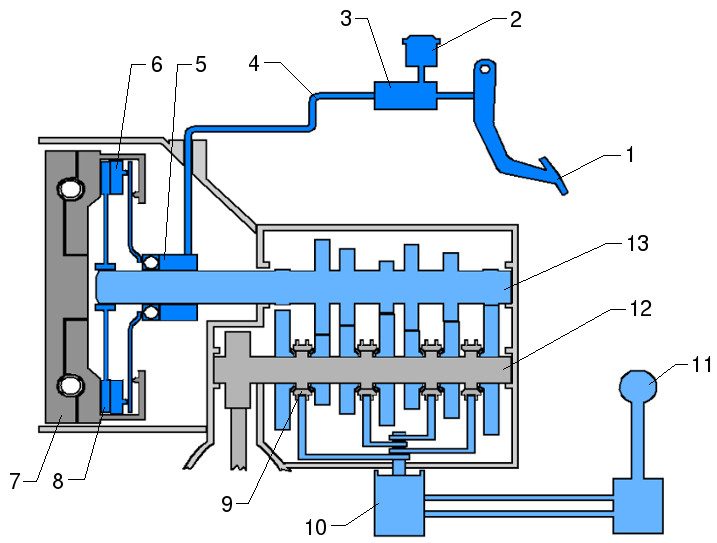
On a vehicle with manual transmission, the engagement/disengagement of the clutch and gears are controlled directly by the driver, through the clutch pedal and gear shift lever. On an AMT, there is no more clutch pedal and the gear shift lever is replaced by program selection lever. The actuation of the clutch and gears is done with electrohydraulic of electric actuators, controlled through electronic signals coming from an electronic control module.
- clutch pedal
- clutch actuation fluid reservoir
- master cylinder
- high pressure pipe
- slave cylinder (concentric slave cylinder, CSC)
- (clutch) pressure plate
- dual-mass flywheel
- friction (clutch) disc
- synchronizer
- gear actuation mechanism
- gear shift lever
- output shaft
- input shaft
An automated manual transmission (AMT) is basically a manual transmission (MT) with electronic controlled clutch and gear actuators. To convert a manual transmission into an automated manual transmission, the clutch pedal (1) and the gear shift lever (11) are replaced by electrohydraulic or electric actuators.
First generations of AMTs were based on the concept of “add-on“, which means that an existing, already designed MT was converted into an AMT by adding external electronic controlled actuator mechanisms. Later generations of AMTs had the actuators embedded into them from the early stages of the design phases.
A conversion from a MT to an AMT requires:
- replacement of the clutch actuation mechanism with an electrohydraulic / electrical actuator
- replacement of the gear actuation mechanism with an electrohydraulic / electric actuator
- integration of an electronic control module
- integration of: input shaft speed sensor, clutch position sensor, gear selection and engagement position sensors, shift lever position sensor, fluid pressure and temperature sensor (in case of an electrohydraulic actuation system)
- engine control software which allows torque control during gearshift
Depending on the vehicle manufacturer, the automated manual transmissions have different commercial names but, in the end, they are the same in terms of functionality:
- Easytronic (Opel)
- Quickshift, Easy-R (Renault)
- Sensodrive (Citroen)
- Selespeed (Alfa Romeo)
Gear shift process
On a manual transmission, starting from the neutral point (N) of the shift lever, the gear shift process can be split in two phases:
- gear selection (also called gate selection): when the corresponding gear plane/line is selected
- gear engagement: when the upcoming gear is actually engaged
For example, to engage the 1st gear, the shift lever is first moved to the left, in the 1-2 plane, and then pushed forward.
Since the gear engagement is a combination of two movements, on different axes, an AMT requires:
- 2 actuators for the gear shifting process
- 1 actuator for the clutch engagement/disengagement
An actuator can be defined as a device which converts an electrical signal (send by an electronic control module) into a physical action (translation or rotation). Actuators can be a solenoid operated valve that controls fluid pressure or an electric motor which rotates a gear wheel.
Easytronic AMT (Opel)
The Easytronic automated manual transmission has an hybrid electrohydraulic actuator for the clutch engagement/disengagement and two electric actuators for gear shifting (selection and engagement).
- clutch (self-adjusting clutch, SAC®)
- clutch slave cylinder (CSC)
- electric motor (direct current) – clutch actuation
- piston (inside cylinder)
- gear shift mechanism
- electric motor (direct current) – gear selection
- electric motor (direct current) – gear engagement
When the clutch position is controlled by an electronic control module, it is important to either keep the mechanical parameters of the clutch constant or adapt the control algorithms to clutch wear.
The friction disc wears during service life, which makes the clutch stroke (open/closed distance) to be variable (smaller for a new clutch). For the electronic control module this is seen as a perturbation of the clutch engagement/disengagement process and might result in faulty clutch actuation. There are two ways to overcom this:
- mechanical self adjustment of the clutch
- learning of the clutch stroke and adapting the control algorithms
The clutch (1) is automatically adjusting its stroke (open/closed distance) function of the wear of the friction disc. It’s called a self-adjusting clutch (SAC) and it’s produced by LuK (Schaeffler).
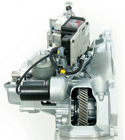
- actuator case with integrated transmission control unit (TCU)
- worm (gear)
- worm wheel
- DC electric motor (with brushes)
- piston
- outlet pipe (towards CSC)
- inlet pipe (from reservoir)
- connecting rod
The clutch actuator is a mix between hydraulic and electric actuation. When the clutch needs to be disengaged, the electric motor (4) is powered by the TCU. The rotor of the electric motor is directly connected with the worm (2), which is in constant mesh with the worm wheel (3). The rotational motion of the worm wheel is converted into linear motion by the connecting rod (8), which pushes the piston (5) and creates pressure. Through the outlet (6) the fluid under pressure reaches the clutch slave cylinder (CSC) and actuates the clutch.
The hydraulic circuit is made of a cylinder and a piston on the actuator side and the clutch slave cylinder on the other side. The actuation force of the clutch is directly proportional with the fluid pressure in the circuit.
The position of the clutch is therefore controlled by the fluid pressure in the hydraulic system, which depends on the position of the direct current (DC) electric motor.
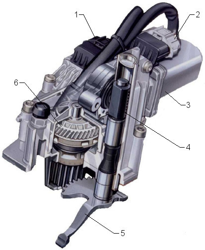
- electrical connector for gear engagement electric motor
- electrical connector for gear selection electric motor
- gear selection electric motor
- rack
- gear engagement finger (for gear engagement)
- gear wheel
From the neutral position, if a gear needs to be engaged, the gear selection motor (3) moves the rack (4) up and down. When the appropriate gear plane (gate) has been selected, the gear engagement motor (1) will rotate the gear (6) which will rotate the gear engagement finger (5). The sliding sleeves of the gear synchronizers are connected through a fork and a shaft to the gear engagement finger (5). When the gear engagement finger (5) is moved to one of its end positions, the gear is engaged.
The electric motors have integrated position sensors. Based on the position information, the transmission control module regulates the electrical power of the motors in order to bring them in the expected position.
Easytronic 3.0 (Opel)
The new 5-speed automated manual transmission from Opel/Vauxhall, Easytronic 3.0, is using electrohydraulic actuators for clutch and gear shifting. The new AMT can also support engine Stop & Start functions.
The maximum input torque of the transmission is 190 Nm and can be fitted on 1.4 L gasoline engines or 1.3 diesel engines. The shift forks and synchronisers are common with the manual transmission variant.
The electrohydraulic module responsible for the clutch and gear actuation consists mainly of: pump (with electric motor), hydraulic pressure accumulator, fluid reservoir and solenoid valves block. Also, the gear selection and engagement position sensors and the fluid pressure sensor are integrated within the same module, without wiring. This brings advantages in terms of cost, mass, packaging and system reliability.
To measure the input shaft speed, the new automated manual transmission is equipped with a speed sensor, using the Hall effect principle. The 4th gear wheel serves as the target for the speed sensor, therefore a separate target wheel is not required and all shafts can be used unchanged, in the AMT or MT applications.
The transmission parameters are summarized in the table below.
| Parameter | Value | |
| Maximum torque [Nm] | 190 | |
| Gear ratios [-] | 1st gear | 3.727 |
| 2nd gear | 2.136 | |
| 3rd gear | 1.323 | |
| 4th gear | 0.892 | |
| 5th gear | 0.674 | |
| Reverse gear | 3.308 | |
| Final drive gear | 4.188 (4.625), depending on application | |
| Center distance [mm] | 180 | |
| Length [mm] | 365 | |
| Mass (dry) [kg] | 39 | |
| Transmission fluid volume [L] | 1.6 | |
The clutch position is controlled with a proportional electrohydraulic valve, which regulates the (oil) pressure in the concentric slave cylinder (CSC). The CSC is also equipped with a contactless position sensor which uses a Hall effect sensitive element.
The advantage of position measurement directly on the CSC is that dynamic and temperature-caused effects in the hydraulic line are included in the control loop, as opposed to measuring the position on a master cylinder. The disadvantage is that the CSC’s axial pulsation during engine running is also detected by the position sensor and superimposed over the travel signal. Suitable filtering compensates for this effect during processing of the raw signal in the transmission controller.
Quickshift AMT (Renault)
The first generation of Quickshift automated manual transmissions (AMT) were integrating an electrohydraulic actuation module on top of a manual transmission (MT). The clutch and gear positions were entirely regulated by the transmission control module (TCM), through fluid pressure. There are no electric motors in the system, for clutch and gear actuation, but only electronic controlled solenoid valves.
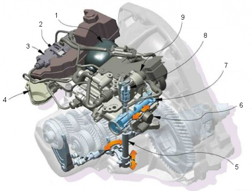
- hydraulic accumulator
- cylinder with piston for clutch actuation
- fluid pump assembly (actuated by an electric motor)
- clutch position sensor
- gear selection and engagement rod
- gear engagement position sensor
- cylinder with piston for gear engagement
- cylinder with piston for gear selection
- gear selection position sensor
The clutch and gears actuation is performed using fluid under pressure. The fluid pump assembly (3) creates pressure in the hydraulic system, up to 30-40 bar. The hydraulic accumulator (1) has the role of storing the high pressure fluid. After several gear shifts or clutch actuation events, the pressure in the system (read by a pressure sensor) will decrease. The pressure is restored back at the nominal level by the electric pump.
When a gear shift is performed, the transmission control unit performs the following operations:
- regulates the pressure in the CSC, through the actuator (2), in order to open the clutch
- increases pressure in the cylinder with piston for gear selection (8)
- increases pressure in the cylinder with piston for gear engagement (7)
- regulates the pressure in the CSC, through the actuator (2), in order to close the clutch
All the pressure regulation is done through electrohydraulic valves and managed by the TCU.
- hydraulic accumulator
- electronic control module (mounted on the electrohydraulic valves block)
- fluid reservoir
- electric motor (for pump actuation)
The first generation of Quickshift AMTs is using an electrohydraulic “add-on” module, supplied by Magneti Marelli. This module is mounted on top of an existing manual transmission and is replacing the external clutch and gear actuation mechanisms.
Easy-R AMT (Renault)
The new generation of automated manual transmission from Renault, Easy-R, uses electromechanical actuation instead of hydraulic technology, for “enhanced flexibility and swifter response”, while the number of components has been reduced by around 25 % in order to deliver “greater reliability and simplify servicing”.
The clutch actuation is performed by a single electric motor. The gear selection and gear engagement are, each, actuated by a electric motors. In terms of packaging, the clutch actuation module is integrated with the transmission control unit, while the gear actuators come together in a separate module.
Sensodrive AMT (Citroen)
The automated manual transmission from Citroen, Sensodrive, is similar with Easytronic (Opel) in terms of components and working principles. The clutch actuation is performed using one electric motor, the gear selection and engagement is using two electric motors.
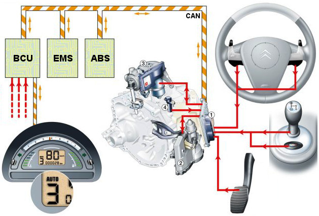
In an AMT, when a gearshift is performed, both the engine and transmission electronic control modules are working together and exchange information. The gear change has to be performed even if the driver has the accelerator pedal pressed and the engine delivers torque.
In order to synchronize the engine output torque with the clutch and gear positions, the engine management system (EMS) must exchange torque and speed information with the transmission control module (TCM). All the information is exchanged on a communication bus called Controller Area Network (CAN).
The TCM also exchanges information with the body control unit (BCU) in order to display to the driver the driving mode and the engaged gear.
- transmission control module (TCM)
- clutch actuation module
- gear actuation module
- shaft speed sensor
The current trend in the automotive industry is to use only electric motor actuation systems for clutch and gears. The main reason is that, as electronics and electric technology is developed, it has become possible to design and manufacture low price, reliable, high efficient electric actuators with the required level of performance (e.g. response time). These actuators can also deliver the required actuation force with minimum amount of electric power.
Gear actuation modules come also with a level of embedded diagnostic functions. If there is an issue with the electric motors or position sensors, the transmission control module is informed and takes the appropriate measures to guarantee the safety of the vehicle and the integrity of the components.
Driving modes
Nowadays, for a driver, is quite difficult to distinguish between an AMT, AT or DCT. If at a hardware level their are different in terms of layout and components, at the function (software) level, they all behave similarly.
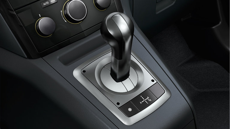
In an AMT vehicle the driver has an accelerator pedal, a brake pedal, a program / gear selector lever and (optional) steering wheel paddle shifters. With the lever, the driver can select at least four modes:
- Automatic (also called Drive) (A, D)
- Manual (M or +/-)
- Neutral (N)
- Reverse (R)
In the Automatic mode (also called Drive mode), both the decision to shift gears and the actual gear shifting is performed by the transmission control module, without any intervention or input from the driver. The main criteria for a gear change is calculated function of the vehicle speed and engine load (accelerator pedal position).
In Manual mode, the driver can decide when to shift gears. By tipping “+” a upshift if requested and by tipping “-” a downshift is requested. In this mode, there are some protection functions active, which will shift the gears even if the driver didn’t requested it. For example, if the engine speed is too high, an upshift will be performed and, if the engine speed is too low (not enough engine torque), a downshift will be performed.
Most of the vehicles with AMT have a Snow mode. This mode is useful in driving conditions with low friction of the road. In this mode, for vehicle launch, the 2nd gear is selected instead of the 1st gear. This way, the traction force at the wheel is limited and wheel slip is avoided.
The main advantages of an automated manual transmission (AMT), compared with a manual transmission (MT), are:
- more comfortable driving (the gear shifting is done automatically)
- better fuel economy (the engine is kept in the most fuel efficient operating zone, through the gear ratio)
- wear diagnostic (the electronic controlled actuators can measure clutch wear and inform the driver)
The disadvantages is the higher price of the transmission which translates in slightly higher price of the vehicle.






Phill
How does the creep function work. Is it just slipping the clutch to allow low creep speed
Anthony Stark
Yes, it is slipping the clutch. Depending on how is calibrated it can slip at the beginning, to launch the vehicle and could fully engage later, which means that the vehicle is “idling in gear”. During the clutch slip control, the engine torque is also controlled to make sure that the engine is not stalled by the high load.
Geoff Lane
On my new 2021 Picanto it suggests creep is disengaged when brake is used (either foot brake or handbrake), so guessing when stationary and brake applied clutch fully disengaged, when brake released creep initiated until speed sufficient to fully engage.
Winston Poole
The 2020 model i10 has automated manual transmission , is it fully electrically actuated?
Thanks.
Mohammad
Really helpful thank you
Suresh Nabar
Hi! I have a Honda Civic 1.8SMT. I wish to change it to ATM. Please advice if it is possible and what would be the cost.